

A Verkle tree is a commitment scheme that works similar to a Merkle tree, but has much smaller witnesses. It works by replacing the hashes in a Merkle tree with a vector commitment, which makes wider branching factors more efficient.
Thanks to Kevaundray Wedderburn for feedback on the post.
Overview
For details on how verkle trees work, see:
The aim of this post is to explain the concrete layout of the draft verkle tree EIP. It is aimed at client developers who want to implement verkle trees and are looking for an introduction before delving deeper into the EIP.
Verkle trees introduce a number of changes to the tree structure. The most significant changes are:
- a switch from 20 byte keys to 32 byte keys (not to be confused with 32 byte addresses, which is a separate change);
- the merge of the account and storage tries; and finally
- The introduction of the verkle trie itself, which uses vector commitments instead of hashes.
As the vector commitment scheme for the verkle tree, we use Pedersen commitments. Pedersen commitments are based on elliptic curves. For an introduction to Pedersen commitments and how to use them as polynomial or vector commitments using Inner Product Argumentss, see here.
The curve we are using is Bandersnatch. This curve was chosen because it is performant, and also because it will allow efficient SNARKs in BLS12_381 to reason about the verkle tree in the future. This can be useful for rollups as well as allowing an upgrade where all witnesses can be compressed into one SNARK once that becomes practical, without needing a further commitment update.
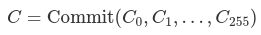
The curve order/scalar field size of bandersnatch is p = 13108968793781547619861935127046491459309155893440570251786403306729687672801, which is a 253 bit prime. As a result of this, we can only safely commit to bit strings of at most 252 bits, otherwise the field overflows. We chose a branching factor (width) of 256 for the verkle tree, which means each commitment can commit to up to 256 values of 252 bits each (or to be precise, integers up to p - 1). We write this as Commit(v₀, v₁, ..., v₂₅₅) to commit to the list v of length 256.
Layout of the verkle tree
One of the design goals with the verkle tree EIP is to make accesses to neighbouring positions (e.g. storage with almost the same address or neighbouring code chunks) cheap to access. In order to do this, a key consists of a stem of 31 bytes and a suffix of one byte for a total of 32 bytes. The key scheme is designed so that "close" storage locations are mapped to the same stem and a different suffix. For details please look at the EIP draft.
The verkle tree itself is then composed of two types of nodes:
- Extension nodes, that represent 256 values with the same stem but different suffixes
- Inner nodes, that have up to 256 children, which can be either other inner nodes or extension nodes.
The commitment to an extension node is a commitment to a 4 element vector; the remaining positions will be 0. It is:
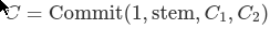
C₁ and C₂ are two further commitments that commit to all the values with stem equal to stem. The reason we need two commitments is that values have 32 bytes, but we can only store 252 bits per field element. A single commitment would thus not be enough to store 256 values. So instead C₁ stores the values for suffix 0 to 127, and C₂ stores 128 to 255, where the values are split in two in order to fit into the field size (we'll come to that later.)
The extension together with the commitments C₁ and C₂ are referred to as "extension-and-suffix tree" (EaS for short).
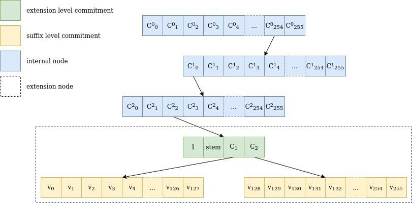 Figure 1 Representation of a walk through a verkle tree for the key 0xfe0002abcd..ff04: the path goes through 3 internal nodes with 256 children each (254, 0, 2), one extension node representing abcd..ff and the two suffix tree commitments, including the value for 04, v₄. Note that stem is actually the first 31 bytes of the key, including the path through the internal nodes.
Commitment to the values leaf nodes
Each extension and suffix tree node contains 256 values. Because a value is 256 bits wide, and we can only store 252 bits safely in one field element, four bits would be lost if we simply tried so store one value in one field element.
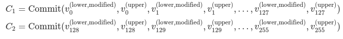
To circumvent this problem, we chose to partition the group of 256 values into two groups of 128 values each. Each 32-byte value in a group is split into two 16-byte values. So a value vᵢ∈ 𝔹₃₂ is turned into v⁽ˡᵒʷᵉʳ⁾ᵢ ∈ 𝔹₁₆ and v⁽ᵘᵖᵖᵉʳ⁾ᵢ∈ 𝔹₁₆ such that v⁽ˡᵒʷᵉʳ⁾ᵢ ++ v⁽ᵘᵖᵖᵉʳ⁾ᵢ= vᵢ.
A "leaf marker" is added to the v⁽ˡᵒʷᵉʳ⁾ᵢ, to differentiate between a leaf that has never been accessed and a leaf that has been overwritten with 0s. No value ever gets deleted from a verkle tree. This is needed for upcoming state expiry schemes. That marker is set at the 129th bit, i.e. v⁽ˡᵒʷᵉʳ ᵐᵒᵈⁱᶠⁱᵉᵈ⁾ᵢ = v⁽ˡᵒʷᵉʳ⁾ᵢ + 2¹²⁸ if vᵢ has been accessed before, and v⁽ˡᵒʷᵉʳ ᵐᵒᵈⁱᶠⁱᵉᵈ⁾ᵢ = 0 if vᵢ has never been accessed.
The two commitments C₁ and C₂ are then defined as
Commitment of extension nodes
The commitment to an extension node is composed of an "extension marker", which is just the number 1, the two subtree commitments C₁ and C₂, and the stem of the key leading to this extension node.
Unlike extension nodes in the Merkle-Patricia tree, which only contain the section of the key that bridges the parent internal node to the child internal node, the stem covers the whole key up to that point. This is because verkle trees are designed with stateless proofs in mind: if a new key is inserted that "splits" the extension in two, the older sibling need not be updated, which allows for a smaller proof.
Commitment of Internal nodes
Internal nodes have the simpler calculation method for their commitments: the node is seen as a vector of 256 values, that are the (field representation of the) root commitment of each of their 256 subtrees. The commitment for an empty subtree is 0. If the subtree is not empty, then the commitment for the internal node is
where the Cᵢ are the children of the internal node, and 0 if a child is empty.
Insertion into the tree
Figure 2 is an illustration of the process of inserting a new value into the tree, which gets interesting when the stems collide on several initial bytes.
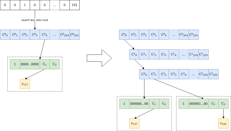
Figure 2 Value v₁₉₂ is inserted at location 0000010000...0000 in a verkle tree containing only value v₁₂₇ at location 0000000000...0000. Because the stems differ at the third byte, two internal nodes are added until the differing byte. Then another "extension-and-suffix" tree is inserted, with a full 31-byte stem. The initial node is untouched, and C²₀ has the same value as C⁰₀ before the insertion.
Shallower trees, smaller proofs
The verkle tree structure makes for shallower trees, which reduces the amount of stored data. Its real power, however, comes from the ability to produce smaller proofs, i.e. witnesses. This will be explained in the next article.